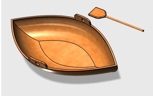
Canoe Project
Measurements
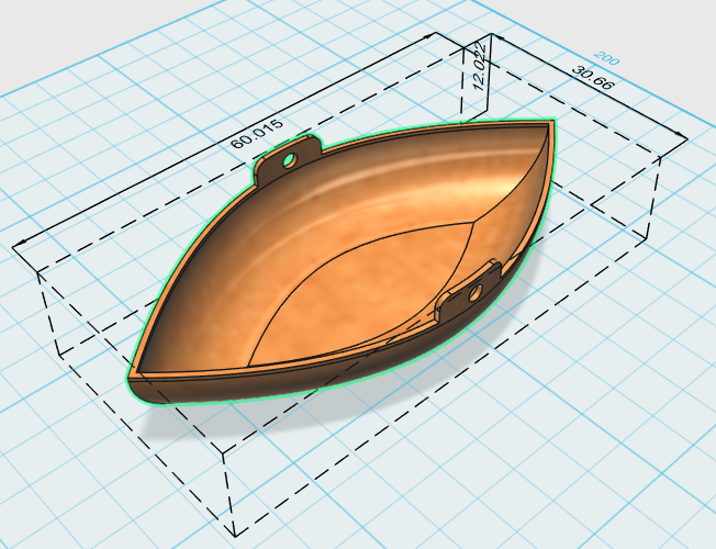
You can find on the previous picture, roughly the dimensions used for this project. To start, we will use some basic tools to sketch primitive 2D shapes that will help in putting us in an easy path to create the object of this project.
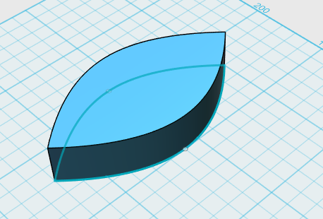
Step 1- Basic Canoe Shape
Here is what the first object to draw looks like (You can use the grid as a reference to replicate this object):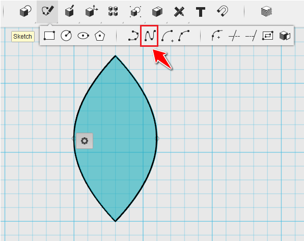
I used 2 Splines. You can choose to draw one Spline, and MIRROR it to find the second half of the image.
Step 2 Making it 3D
Extrude the whole.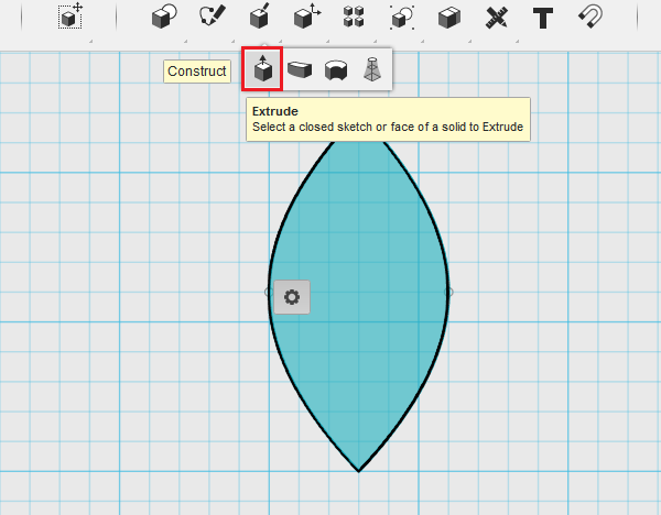
You should end up with the following:
Step 3 Making the bottom curvier.
Use the Fillet command on the lower edges of the object: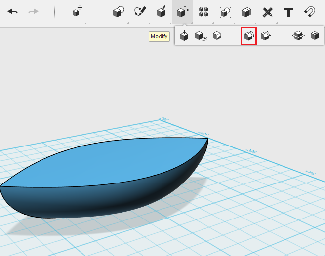
Step 4 Hollowing it out
Use the OFFSET command and use the upper plane surface as you reference: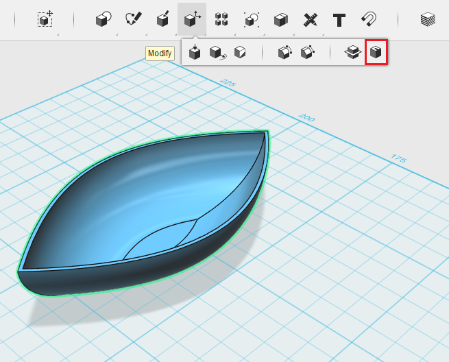
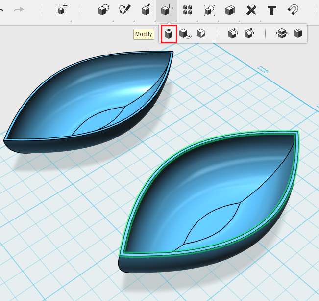
Step 5 Oarlocks
The first thing I want to do is to copy the object and remember the distance I moved the copy from the original. Let’s move linearly the copy 50 units from the original on the right side. (To do this, Select the object, Ctlr+c and Ctrl+v, select the axis of displacement, Enter a distance, and Hit Enter):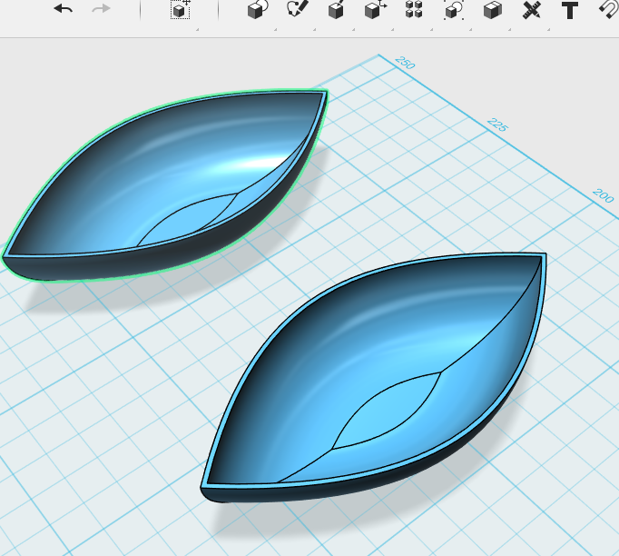
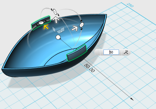
What I want to do now is, pull the upper shape of the canoe with a height of 3 units.
Create a bar crossing the canoe such as shown on the image below.
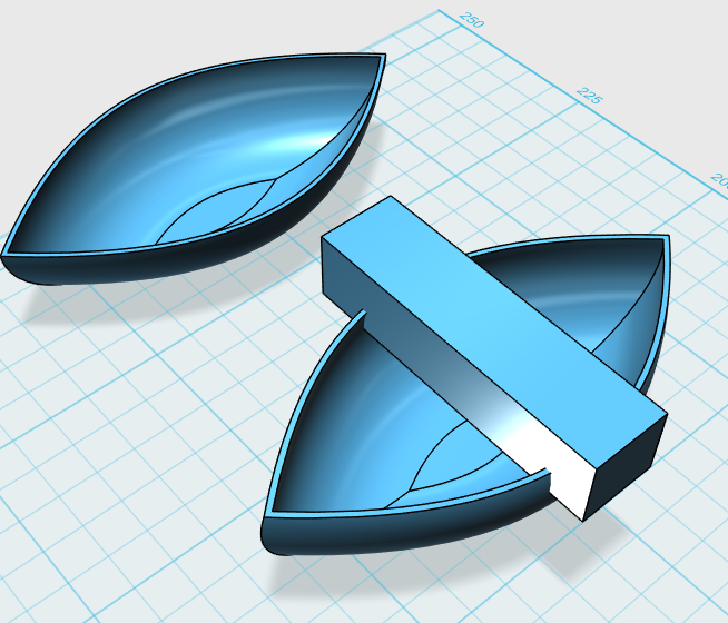
Extract the intersecting shape of the bar + the canoe using the Intersect command:
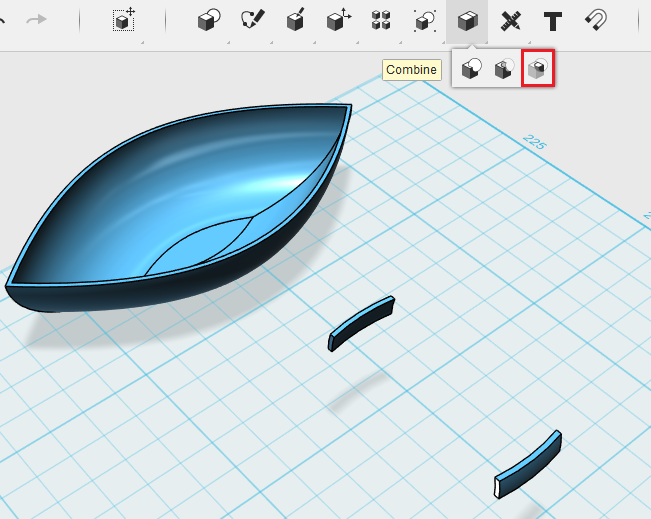
Move back the two pieces to the original object. Remember it has to be moved exactly 50 units back.
Step 6- Making it all one object
Merge the whole.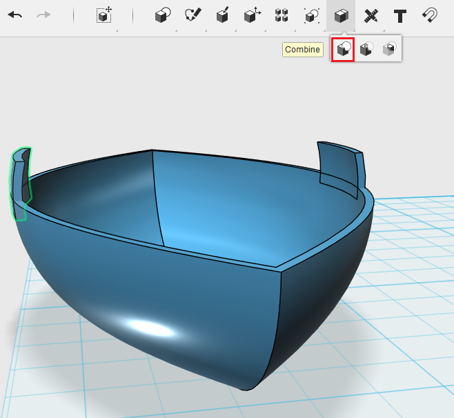
Step 7 Smoothing the edges
Fillet the additional shapes: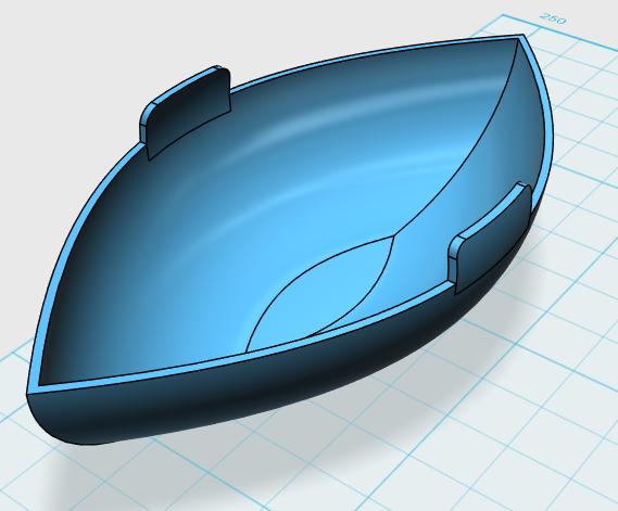
Step 8 Holes, part 1
Create a bar perpendicular to the canoe and place it somehow in the middle of the added shape to create holes for the paddles.
Step 9-Holes, part 2
Subtract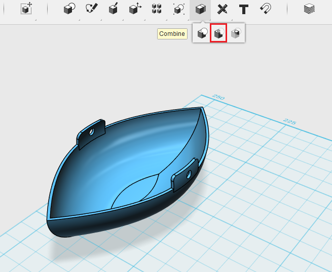
Step 9- Paddles
Now try to design a paddle or 2 paddles that will fit in the oarlocks. Think about the size you'll need.
No comments:
Post a Comment
Note: Only a member of this blog may post a comment.